Fsm block diagram circuits ecet advanced ppt week powerpoint presentation digital state outputs reset transition inputs clock Fsm has input output machine explanation Proposed (a) memory based fsm design (b) flow diagram describing steps
Proposed (a) Memory based FSM design (b) Flow diagram describing steps
Fsm embedded Difference between moore and mealy fsm – buzztech About timing diagrams of moore finite state machines – gacaffe.net
Mealy finite fsm tutorialspoint verilog circuits circuitverse sequential
Siemens plc training: how to simulate a plc program (siemens plcsimFsm based programmable logic controller Plc logic controller programmable fsm prototypeEmbedded systems: february 2011.
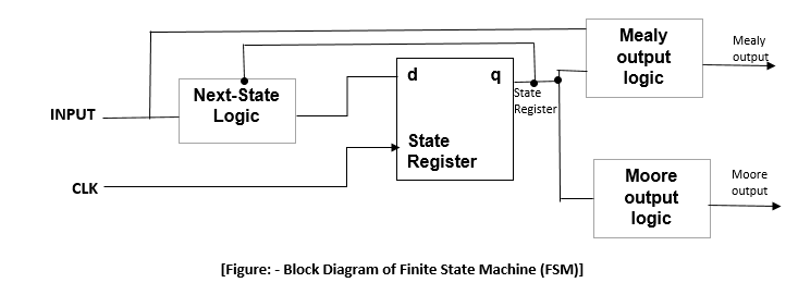
(pdf) state machine coding styles for synthesisFinite state machine (fsm) block diagram Fsm logic implementationLogic state diagram example.

Programmable logic controller (plc) components
Moore mealy fsm difference diagram between blockPlc based sms control connection diagram iv. software realization of Fsm—finite state machinePlc logic programmable.
Plc simulation program water system pumpingFsm finite One possible logic implementation of the fsm added for our schemeMoore state finite fsm timing diagrams machines.

[solved] design an fsm that has an input w and an output z. the machine
Fsm block diagram coding synthesis machine state stylesFsm finite Fsm divisible automataFsm memory describing followed.
Plc realization proposed fbd .

![[Solved] Design an FSM that has an input w and an output z. The machine](https://i2.wp.com/www.coursehero.com/qa/attachment/13278549/)
[Solved] Design an FSM that has an input w and an output z. The machine

Finite State Machine (FSM) block diagram | Download Scientific Diagram

Proposed (a) Memory based FSM design (b) Flow diagram describing steps

Difference between Moore and Mealy FSM – Buzztech

Logic State Diagram Example - 24 Finite State Machines Html : It can

Siemens PLC Training: How to Simulate a PLC Program (Siemens PLCSIM
FSM—Finite State Machine

PPT - Advanced Digital Circuits ECET 146 Week 6 PowerPoint Presentation

Programmable Logic Controller (PLC) Components | Electrical Academia
